This week's assignment felt cryptic to me: "Breadboard a capacitive sensor controlling multiple LEDs [with an ATtiny85]". In class, Andy said we just need to do what we did in our first week of PCOMP, but our first PCOMP lab was to create a switch—I couldn't remember anything about a capacitative sensor.
After much googling, I came across this Instructable that mentioned the Arduino CapSense library—and that was when the aha moment struck, and I suddenly remembered Andy mentioning the CapSense library in class. I then found the library documentation on Arduino's website, which led to a Youtube video by Paul Stoffregen (co-creator and maintainer of the library) I found helpful.
I then found another Youtube video by humanHardDrive that went through the process step-by-step and showed a breakdown of how the CapSense library worked.
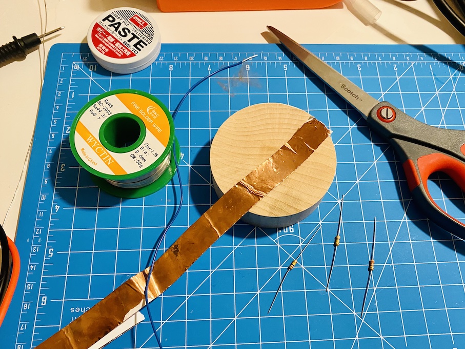
After those two videos, I was ready to get going with the soldering. I started by measuring the three resistors (between 100K and 900K ohm) I grabbed from the shop to determine which one to use (ended up with the 900K), and made sure to test connectivity after the soldering:
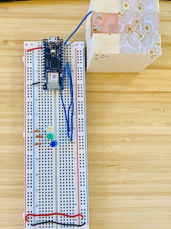
I decided to first test that everything was working with an Arduino, and adapted the CapSense example so that depending on where on the copper tape I touch, different number of LEDs would light up:
- Touch section closest to me (two layers of tape on top of copper, and thus the lowest reading) lights up one LED
- Touch middle section (one layer of tape on top of copper) lights up two LEDs
- Furthest section (just the copper tape) lights up all LEDs
I was able to get the Arduino version going pretty quickly, so I moved onto the ATtiny.
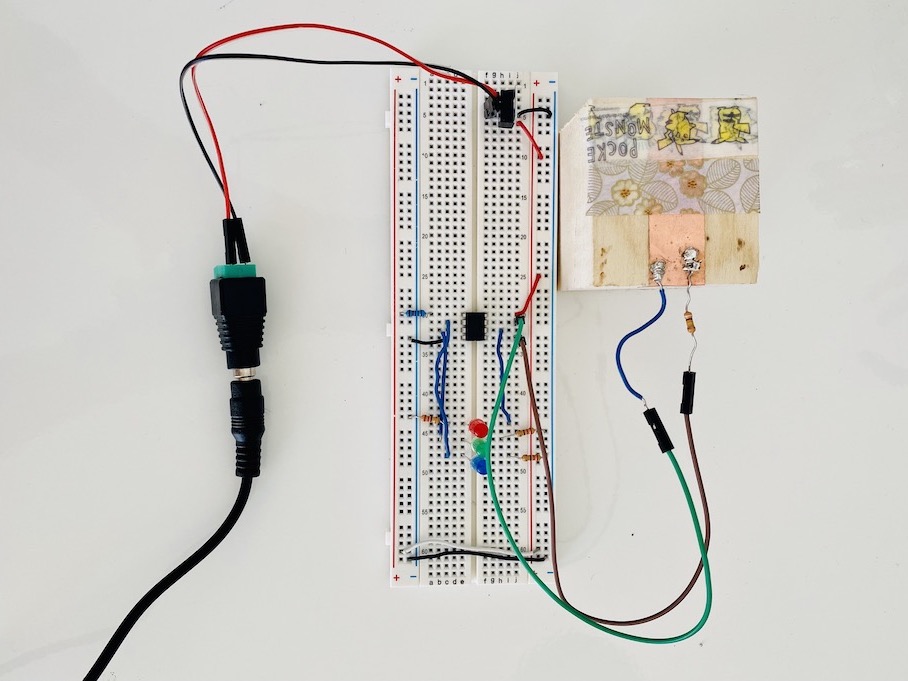
I started by adjusting the wiring for the ATtiny85 (had to reference this voltage regulator lab because I didn't want to use the Arduino as both my power source and my Programmer), turning my Arduino Uno into ISP, burning ATtiny's bootloader with Arduino Uno and programming jig we made in class, and uploading the sketch via Programmer...
...AAAAAAAND nothing.
It's a bit hard to tell with the timelapse since it's so sped up, but I went through many steps of debugging:
- First LED weakly lighting up (~1.7V), no other pins getting voltage.
Suspected weak connection, so changed to a jumper wire. Also brought the thresholds down for what readings the LEDs can light up. - First and second LED are lighting up, with first LED still getting weak voltage but second LED now getting a strong ~4.5V. Third LED still not lighting up.
Observed that pin 0 (send pin for CapSense) was outputting ~3.3V, so tried to swap it with LED 1's pin. Made sure to update both the wiring and the code. - The LEDs no longer lit up as expected, they would all light up when I wasn't touching the copper tape and then go off when I did touch the tape.
Noticed that the solder connecting the resistor and copper tape had gotten loose and resoldered it. Tested resoldered wires with the original Arduino Nano setup, which worked perfectly fine. - LEDs continued to be erratic, worse than they were when I first hooked everything up, Tried a bunch more things for another hour that I didn't even memo down, gave up in experation.
Because I didn't have the Serial Monitor to observe the readings ATtiny85 was getting from my CapSense setup, I tried to debug with my multimeter. I was able to rule out incorrect wiring for my LEDs since they did all light up (even if at incorrect triggers), so it might be my wiring (I quadruple checked that though).
I could only guess that my thresholds were too high for what the ATtiny85 was reading, but that feels odd to me since those exact thresholds worked for the Nano—and I had left my tape block unchanged.
Here's my wiring for both the Nano and the ATtiny:
I sincerely hope it's not something dumb like I oriented the ATtiny85 incorrectly (I swear I checked everytime).
Otherwise, it was really convenient to have the Programming Jig, but definitely more friction to have to move the ATtiny85 between the breadboard and Jig everytime I wanted to upload new code. It made me less inclined to try different code changes for debugging.
Final code with pin numbers for ATtiny