Lab: Tone
This week's lab didn't treat me well at all.
My first regret: I should have checked out the speaker offered at the end of class. I figured that I already had a speaker at home, an older one from two years ago. When I finally managed to dig it back up from our moving boxes, half of it was bent out of shape (husband bent it back, thank you husband!).
After I hooked it up to the Arduino and wrote a line of code to play a tone (tone(pin, 440, 1000), play at 440hz for one second), nothing happened. No sound played.
I puzzled over this on and off for two days. I thought perhaps it had been too damaged by the move and was completely broken. To debug, I tried to measure the voltage coming out of the pin, but the three ITP multimeters I tried didn't give me any readings (which could be that I wasn't using them right?).
So then I tried swapping the speaker with an LED, and that definitely was lighting up, so it wasn't a problem with the output pin. I swapped the speaker back in.
It was around then that Xuan walked by and told me that she thought she could hear the speaker, just extremely faintly. So we theorized that the resistor I had (220ohm) was too strong, and swapped it out with a 100ohm.
Voila! A tiny tiny sound.
So I tried to wire in a transistor to amplify the speaker, and oh boy was that also an adventure. I started out with a MOSFET (?) transistor, and tried to follow the wiring in the lab while at the same time trying to understand what each of the transistor's pins were doing.
Diagram for pins on a MOSFET transistor (presumably since that's the image that kept coming up, middle) and TIP120 transistor (right).
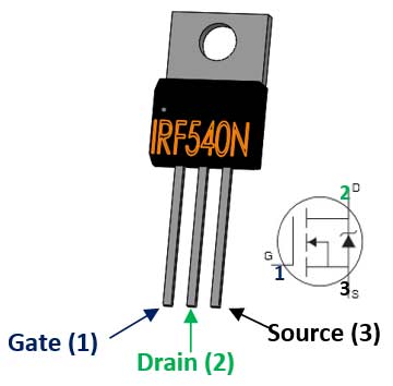
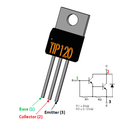
It wasn't until many tries later staring at the image of the MOSFET pins that I realized they were ordered differently from TIP120 pins and the schematic in the lab were for TIP120 pins. As soon as that clicked, things made a lot more sense, that the output from the Arduino was going into the transistor via one pin, getting amplified, and that output then needed to be passed into the speaker (which meant that the lab schematic was a little bit incorrect).
(I'm not sure why the Arduino output goes into the transistor's Emitter pin, and the output is through the Collector pin?)
As soon as I switched to the TIP120 transistor and fixed the wiring, sound started coming out of the resistor again...just not any louder than it was before 😂
The next issue I ran into was when running this code:
void loop() {
  // play the tone for 1 second:
  tone(8, 440,1000);
  // do nothing else for the one second you're playing:
  delay(1000);
}
Theoretically, the speaker should play for a second and then pause for a second, creating a beeping sound. In reality, the speaker played continuously. It wasn't until I tried two drastically different values (play 500ms and pause 5secs) that I heard the pause. I've determined that the sound is continuous if the play duration and the pause is the same length. I tried changing the output pin from a PWM pin (D2) to a non-PWM pin (D8, as specified in the lab code), and nothing changed.
EDIT: OMG I finally read the comment in the lab code and realized, the continuous sound is expected behavior! It seems that tone() is asynchronous and doesn't