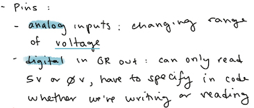
This week's lab is about digital input/output, and analog input.
I feel like I'm starting to get a more intuitive understanding of voltage vs. current, and their relationships with resistance. Here are some notes I took from this week's videos:
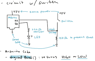
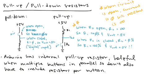
The videos on fixed and variable resistors were a great refresher, and they were especially helpful in cementing my understanding of how voltage reduces relative to resistors. One of the concepts that took me a while to grasp was why the reading for a pull-up resistor would be 5V when the circuit was open and 0V when closed.
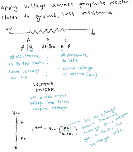
I was confused as to why there would be 5V at the Vout point if the circuit wasn't closed and the current was 0, and at the same time why Vout wasn't less than 5V if it had already gone through a resistor.
I had to review my previous notes a few times to remember that the Vout reading was sandwiched between two resistors, and because when the switch is open the resistance of air is so high, that the ratio of the switch's resistance is so high the first resistor's resistance is near 0%. And thus there is almost no change in voltage going through the first resistor.
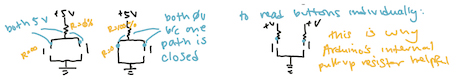
This also helped solve a confusion I had about the advantage of having pull-up resistor programmed into the Arduino. The example given was that if we had multiple switches as inputs to the Arduino and specified that those pins as INPUT_PULLUP, we wouldn't have to wire in resistors for each of those switches. So then I wondered why we couldn't just wire one resistor and split that across the three switches. My husband then explained that this would result in an ANY operation, where as soon as one switch was closed, all of the readings would be the same. That puzzled me for a bit, until I had the same realization as above, about the ratio of the resistors in series determining the voltage reading between them:
I'm now feeling more confident about the relationship of voltage and resistance, and to a certain extent about current too. But I'm still trying to puzzle through why components "consume" current (I learned that LEDs "consume" 20mA), but the current remains the same for a given closed circuit (unless there is a split) and it is the voltage that goes down after each component. And if voltage goes down after a resistor, does that mean that resistor is also "consuming" current? When we say "consuming" current, does it just mean that component is bringing down the current for a circuit?
(Ok I felt pretty confident in my understanding until I wrote down that paragraph lol. I think I'm just still confused about the relationship of voltage and current.)
Labs
Thankfully even with all of that lingering confusion, I had enough understanding to go through this week's labs without much problem.
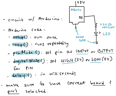
Lab: Digital Input and Output with an Arduino
Lab: Analog In with an Arduino
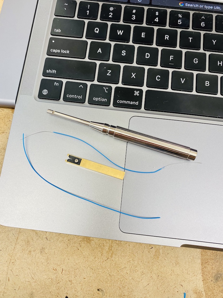
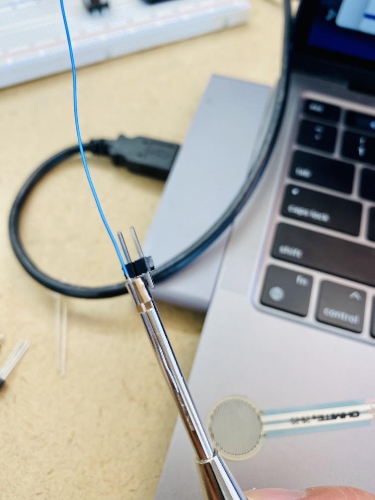
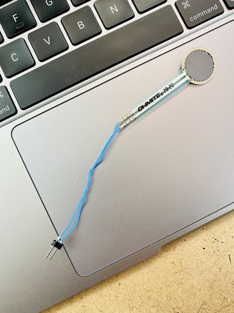
For this lab we played with both a phototransistor (detects light) and force sensing resistor (FSR). It was especially fun to learn how to wire wrap the FSR (we were advised not to plug the FSR directly into our breadboard, and to not solder them either since the leads? are so delicate):
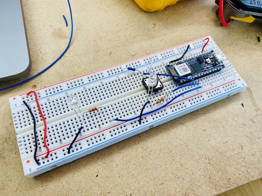
I also made slight adjustments to the lab code for the analog sensors:
- I first tested them for range, and found that they were mostly between 100 and 900 (instead of the 0 and 1024 that the Arduino converts these analog inputs to)
- I then mapped the value from the sensors to a range that's nice for LEDs:
brightness = map(analogValue, 100, 900, 0, 255) - And because that led to some values below 0 and above 255, I constrained the value strictly to a range of 0 and 255:
brightness = constrain(brightness, 0, 255)
And after that, the sensors and LED worked beautifully together:
Lab: Sensor Change Detection
I'm ever grateful that this lab went smoothly especially with the FSRs, and I think it's because I coiled the wire so tightly around all the legs 😆